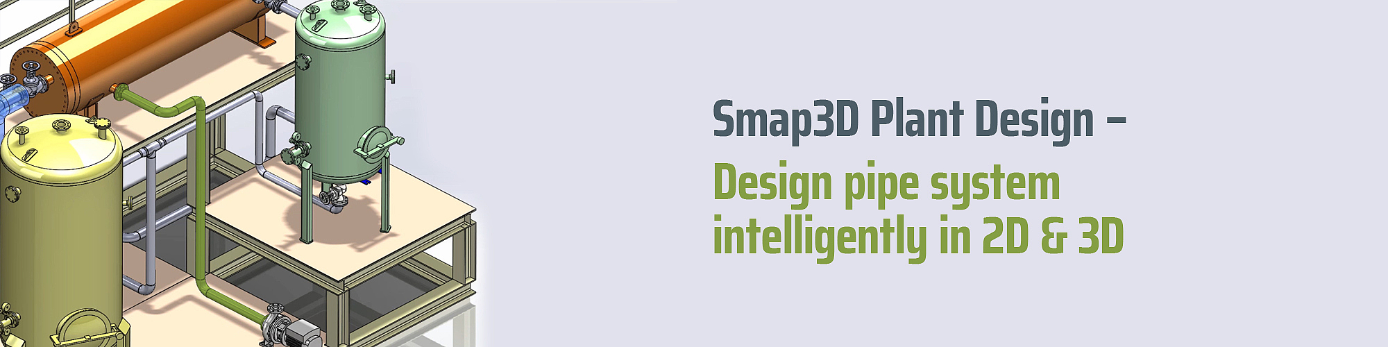
The second link in the process chain is 3D pipeline planning. With Smap3D Piping you automate these and make your 3D CAD system a very powerful 3D plant engineering solution.
Smap3D Piping works as an add-in to the supported CAD systems. The program automates the planning and modification of 3D piping in 3D assemblies. A task that would otherwise have to be done manually by a designer or piping planner in multiple labor intensive steps.
The basis of this highly automated 3D piping design is the use of pipe specifications. Pipe specs are defined as tables for a company, department or project-specific, the relationship of the pipe components (fittings, equipment, etc.) to pipe characteristics (diameter, pressure, temperature, medium, etc.) is determined once. The software contains additional functions and settings for each pipe spec. These also provide for an automated design process.
The piping engine checks the necessary parameters (e.g. connection type maximum and minimum pipe lengths) defined in the pipe spec and uses this information to automate the creation of the pipe assembly. The pipe specification is stored in a central location. This makes it easy to;

Smap3D Piping comprises all the necessary functions for construction, maintenance and management of the pipe spec definitions (Pipe spec editor). Pipe spec 'samples' are delivered with the software. These can be directly used or modified according to individual requirements.
A user draws and defines the required pipe system route as a path with 3D lines (basic functions in the CAD system). The Smap3D piping engine analyses the line segments into a logical pipeline path. A pipeline path describes the route of a 'continuous' piping system from one connection to another, regardless of how many line segments the path is made up of. Further new pipeline paths begin at each branch. Pipeline paths are associative with the sketched 3D line elements of the CAD system. Pipeline paths form the basis for the generated 3D pipeline, made up of fittings and pipes.
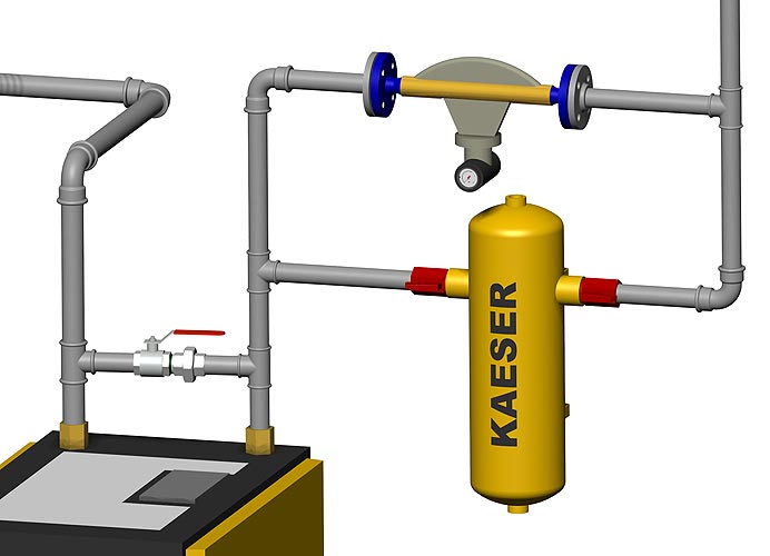
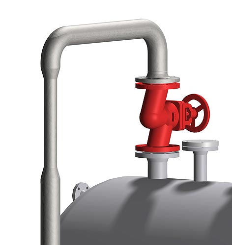
Smap3D Piping automatically generates the complete piping system according to the required pipe spec, its diameter, as well as other pipe system characteristics. In the process, the software automatically places the fittings necessary (e.g. bends, tees, flanges, gasket) for the pipeline route for multiple situations. This saves time and process reliability.
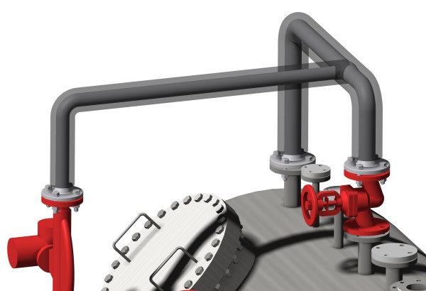
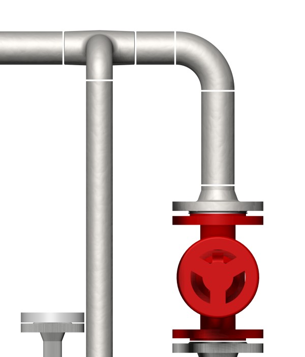
The insertion of additional components (e.g. fittings and instruments) in an existing pipe system is easily possible. Smap3D Piping draws from the utilized pipe spec definitions in the construction of the pipe system and permits only the installation of the appropriate specific components.
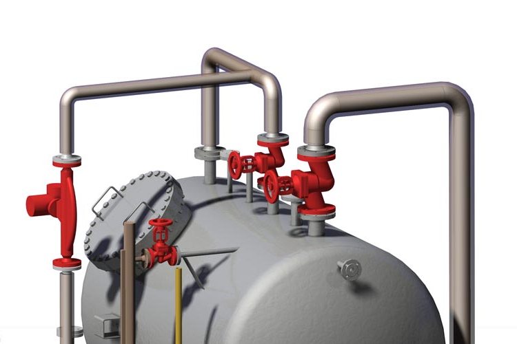
Subsequent to their placing, Smap3D Piping recognizes the new situation and update the pipeline automatically. This method of operation achieves a high level of process security in 3D pipe system planning.

In alterations of the pipe system route (programmed toolpaths) the updating of the constructed pipeline (missing or superfluous fittings and pipes) is carried out fully automatically using the 'knowledge' of the utilised pipe specs.
In alterations to the composition of existing pipelines, for example, in changes to the pipe spec, the diameter, or another pipe spec feature, Smap3D Piping proceeds in the same way and uses the memorised definitions from the pipe specs.
For the generation of reduced or extended pipelines the user must determine only the required diameter and position of the reduced or extended components. The placement of the components as well as the complete modification of the changed pipeline parts to the new diameter are carried out by Smap3D Piping.
In all automatisms offered by Smap3D Piping, the user is still in the position to extend and edit a pipe system according to his individual requirements, with the use of different functions, e.g. 'Use undefined components', 'Place parts'.
Within Smap3D Piping a large number of automatic placement options (QuickPlace methods) for fittings in 3D pipelines are available.
The most important of these are the automatic placement of:
Further intelligent tools and options to assist users are:
When constructing pipelines with pipe specs, Smap3D Piping can also be used to create any non-round profils. Cable ducts, routes, air ventilation ducts etc, can be quickly and efficiently built in the 3D assembly. In the process, the software uses similar fully automatic placement routes, as with round profils.
The most important functions are the automatic placement of

As a special function extention, the alignment of the particular components (left/right, as well as up or down) is taken into account.
and much more…
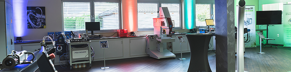
With "The Connected Pipeshop", together with our partners Pipe Bending Systems, Polysoude and T-Drill, we have created a complete solution for pipe manufacturers and plant engineers that covers the entire process from planning to the production of pipes and pipelines.
This ingenious, unique solution will convince you: online or at a workshop in our showroom. Experience the individual components and let's talk about how this solution can also be used profitably in your company.